Notes
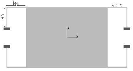
The bent beam is formed by two spring segments perpendicular to
each other, joined at the corner of the central mass as shown in the picture.
The two segments of the beam can have different length, but is assumed to be
equal. The mass is suspended on four such bent beams. In the analysis only a
single beam is considered, and depending on the number of bend beams used in
the suspension the effective spring constant can be calculated.
If the spring constant of one beam is k1 and the second spring is k2, and if they are connected in parallel, the effective spring constant
Kparallel = k1 + k2.
If the two springs are connected in series the effective spring constant is
1/Kseries = 1/k1 + 1/k2
The suspension allows the in-plane movement of the mass in X and in Y direction. It also has an out-of-plane movement perpendicular to the plane of the mass in Z direction. The stiffness of this suspension in all the three axis directions can be found out using this design interface. Since the beam segments have equal length and cross-section, the stiffness in X and Y axis are the same.
The X-Y plot shows the variation of in-plane stiffness (stiffness in X and Y) with the ratio of length to width (len / w) of the beam when the thickness is held constant at the given value. The 2D and 3D surface plot shows the out-of-plane deflection of the bent beam suspension.
