Notes
Diaphragms or membranes as it is sometimes called, form the basic structural
element of MEMS pressure sensors. They are easy to fabricate, offer good
dynamic response and can be used over a wide range of pressures. To improve
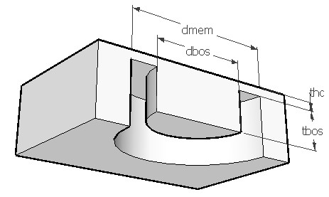
sensitivity and linearity of a flat diaphragm, the center portion of the
membrane is often made thicker so as to form a bossed diaphragm as shown in
the figure. Such a
diaphragm would exhibit higher stresses for the same deflection or lower
deflection for the same stress levels. This makes the bossed design more linear
when compared to a flat diaphragm. Also the thin annular area allows
concentration of stress to improve the sensitivity of the device. It is
particularly useful in sensing low pressure signals. The boss also provides
over load protection. The boss ratio 'dbos/dmem' should be greater than 0.15
and thickness ratio 'tbos/thc' should be greater than six for the boss to be
effective.
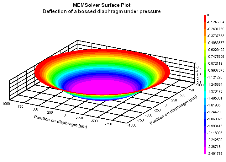
This design interface can be used to determine the maximum stress and deflection of a bossed round diaphragm. In this analysis the outer perimeter of the diaphragm is held firmly and a uniform pressure is applied from top. The applied pressure will deflect the diaphragm till the elastic forces balance the pressure. The maximum displacement of the boss is calculated. The radial stress at the outer perimeter and inner perimeter near the boss are same but opposite in sign. The maximum strain corresponds to the maximum radial stress.
The plot shows the deflection of the bossed diaphragm under pressure. The X axis gives the position from the center towards the outer perimeter for the top fiber of the diaphragm. The deflection flattens off where the boss starts. Using the cross hair tool, the defection at any distance from the center can be calculated.