Notes
Air film damping plays a significant part in the design of micro electro
mechanical devices. If a stationary surface is placed in close proximity to a
mass or another surface which is allowed to move normal to its plane,
the air in between the mass and the stationary surface will be squeezed when the
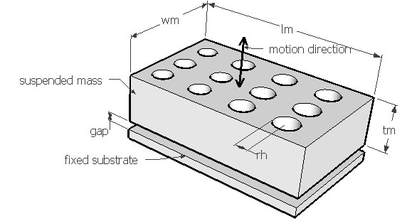
suspended mass moves towards the stationary surface developing a pressure gradient across the width
of the mass. This will push the air out of the gap. Alternately, when the
mass moves away from the stationary surface, the pressure in the gap is reduced and
air flows into the gap. The work done in this process would reduce the energy
of the suspension and thereby the air acts as a damper and the process is
called squeeze film damping.
If a device is underdamped, reducing the gap would improve the damping. But if the part is over damped, increasing the gap might help. But in such situations, the gap cannot be increased beyond a certain limit to ensure overload protection for accelerometers or specified electrostatic force in actuators. In such cases etching some holes on the movable mass would allow the trapped air to escape to bring the damping to acceptable levels. The holes also allow etching of the sacrificial layers to facilitate the release of the suspended plate.
Forces on the moving surface from gas film can be obtained from modified Reynolds equation. The coefficient of damping force can be calculated from this provided the air gap is known. If free vibration frequency of the microsuspension is known, the damping ratio can be calculated from it for that particular mode of vibration. The natural vibration frequency can be estimated under Vibration > Free vibration. The vibration mode should be such that the movement of the suspended mass would squeeze the air out of the gap.
This design form can be used to estimate the coefficient of damping force for the given air gap and plate design. Damping ratio is calculated for the given vibration frequency. It is assumed that the mass is thick and larger than the diameter of the hole. The fixed substrate is considered only on one side of the mass. The quality factor is calculated from the damping ratio for slight damping.
The plot shows the variation of damping ratio with the air gap thickness for a suspended mass with and without damping holes. When the mass gets thicker, the radius of the hole should be increased to make the damping holes effective. Using the crosshair tool, the damping ratio for any air gap thickness upto 20µm can be estimated. It can be used to calculate the air gap that would give a damping ratio of 0.7 for optimum damping of a harmonically forced vibration and a comparision can be done between a hole and no hole versions.