Notes
Diaphragms or membranes as it is sometimes called, form the basic structural
element of MEMS pressure sensors. They are easy to fabricate, offer good
dynamic response and can be used over a wide range of pressures.
This design interface can be used to determine the maximum stress and deflection of a square diaphragm. In this analysis the outer edges of the diaphragm are held firmly and a uniform pressure is applied from top. The applied pressure will deflect the diaphragm till the elastic forces balance the pressure. The maximum displacement is at the center of the diaphragm. Assuming that one edge of the diaphragm is parallel to the X axis, the stress distribution along the X axis is calculated. The maximum stress is found at the edge of the diaphragm. The maximum strain is calculated at that spot, which is strain along X axis.
The plot shows the stress distribution over the surface of the diaphragm along the X axis. It shows that the maximum stress is at the outer edges which is positive and tensile. This decreases and crosses over into a negative or compressive stress which reaches a maximum at the center of the diaphragm. This is for the top fiber of the diaphragm for top side pressure. Using the cross hair tool, the stress in X axis at any location along the length of the diaphragm can be estimated.
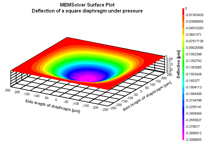
The 2D and 3D surface plots show the deflection of the membrane under pressure.