Notes
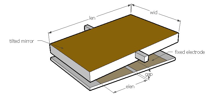
Use this design form to estimate the pull-in voltage and balanced angular
displacement of an electrostatic torsion bar actuator. The actuator typically consists of a
rectangular plate suspended from two torsion bars. The electrodes are placed
symmetrically on the plate or below it so that voltage applied to one of the
electrodes will shift the plate to one side due to electrostatic force. This
driving scheme is often used in MEMS based optical mirrors. When the
applied voltage is higher than the pull-in voltage, the actuator will become
unstable and the plate will tilt to one side and hit the fixed electrode. This
design form can be used to predict
the pull-in voltage and the critical angle of the plate at the pull in
voltage. Also the angular displacement at the given voltage can be predicted.
The actuation torque corresponds to the balanced angular displacement and
applied voltage. The maximum torque that can be generated by the actuator
corresponds to the pull in voltage and critical angular displacement.
The plot shows the relation between the applied voltage and the angular displacement of the plate. The plot can be used to determine the angular displacement for any applied voltage. The maximum voltage is the pull-in voltage and the corresponding angular displacement is the critical angular displacement. After the pull-in state is reached, the plate will remain in the tilted pulled in state till the voltage is reduced below a certain level called holding voltage. That is the voltage corresponding to the maximum angular displacement shown on the graph which is at the extreme right.